← FRC mechanisms

Team Forte / 2025 Reefscape

Elevator

A proven FRC architecture, reworked around our robot’s geometry, local components, and build-season constraints.

My work spanned CAD adaptation, vendor fabrication coordination, and assembly. The central design decision was where this tall mechanism could actually fit.

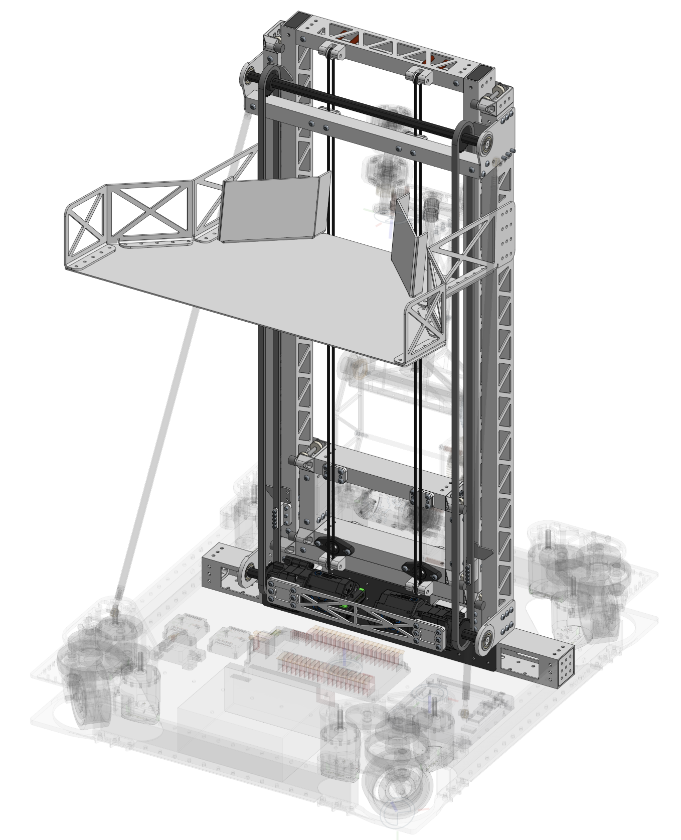
CAD view of the 2025 elevator installed on a transparent FRC robot chassis
2025 elevator in the full robot CAD assembly. Chassis and drivetrain shown transparent.
Competition targetReef L4
Approximate full height1,596 mm
Beam mass reduction24–30%
Build statusAssembled

Make a known mechanism work on our robot.

The 2025 robot needed to raise its pivoting arm to the Reef’s L4 scoring level. A two-stage elevator was a practical starting point, but the reference geometry could not be dropped into our chassis unchanged.

I adapted the CAD, converted the structural and fastening details to parts we could source locally, prepared components for manufacturing, and assembled the elevator. The design had to fit beside the swerve modules and electronics while remaining light, stiff, and serviceable during competition.

01CAD and packaging
02Metric conversion
03Fabrication coordination
04Assembly

The architecture drew from established FRC elevator examples, including two-stage and three-stage reference assemblies. This case study covers our robot-specific adaptation.

The elevator’s position set the arm’s length.

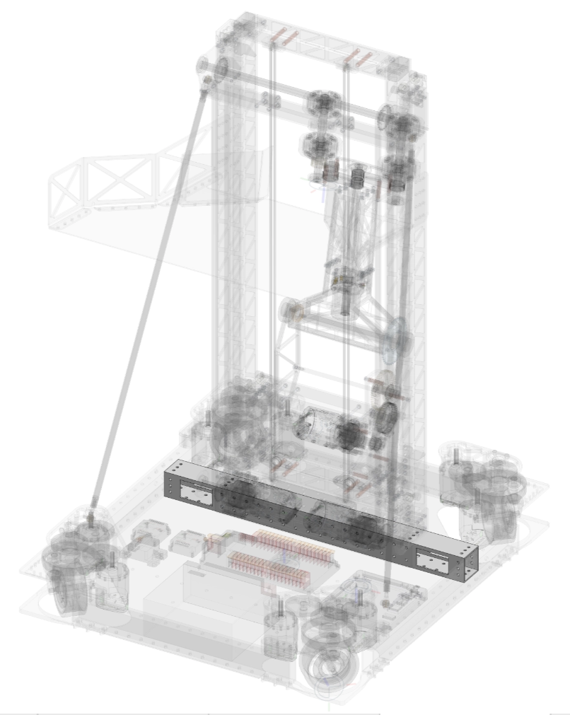
A 50 × 50 mm crossbeam bolted to the chassis supported the elevator base. Moving the elevator farther forward would have shortened the pivoting arm, but the swerve modules and electronics occupied that space.

Keeping the elevator farther back forced a longer arm. That one packaging choice affected arm loading, stiffness, and the geometry of the entire robot.

Integration tradeoff Drivetrain clearance elevator position arm length
Transparent CAD view showing the elevator base mounted to a crossbeam among the robot's swerve modules
The transparent assembly exposes the 50 × 50 mm mounting beam and the space claimed by nearby systems.

Every change had to survive fabrication and assembly.

01

Metric hardware, functional geometry

The reference design used common imperial FRC stock and hardware. I rebuilt the structure around 25 × 50 mm rectangular tube and metric fasteners, bearing blocks, and plate dimensions. The 12.7 mm hex shaft remained because compatible FRC parts were available locally.

This changed hole patterns, bearing spacing, and support geometry; it was a component-level redesign rather than a unit conversion.
02

Guidance without binding

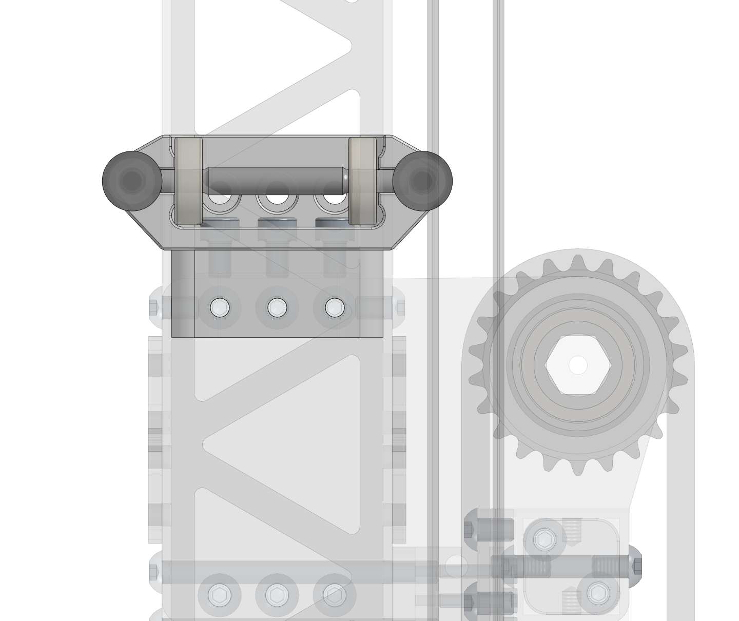
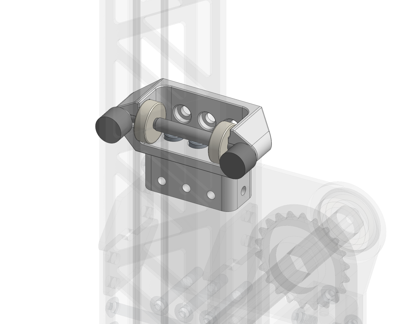
Custom bearing blocks guide the sliding stages around the rectangular tube. Side bearings constrain lateral movement; smaller bearings contact the broad face. The design targeted roughly 0.1 mm of clearance to limit wobble without making the mechanism bind when parts were imperfect.

PETG-CF printed blocks checked fit and assembly first. The final blocks were CNC machined from 6061 aluminum by a vendor and tapped by hand at school.

Front CAD view of the elevator's bearing guide and adjacent drive sprocket
Guide around the 25 × 50 mm tube
Angled CAD detail of the custom bearing block with side and face-contact rollers
Custom bearing block assembly
03

Remove mass where it matters

I used repeated triangular cutouts in the elevator beams, keeping material along the edges and primary load paths. The project notes estimate a 24–30% mass reduction per beam, depending on the cutout layout.

Two diagonal rods brace the top of the elevator back to the chassis. That triangulation reduced global movement without changing the sliding mechanism.

Long CAD side view of the elevator beam with a repeated triangular lightweighting pattern
Triangular cutouts in a vertical elevator member

Two motors. Two extension stages.

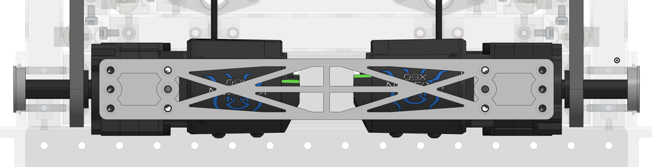
Two Kraken X60 motors with 5:1 MAXPlanetary gearboxes drove the first stage through chain. Dyneema string actuated the second stage, keeping the upper assembly comparatively light.

The approximate full height was 1,596 mm from the bottom to the top of the mechanism. The exported project notes describe smooth travel and about 3 mm or less of wobble at full extension.

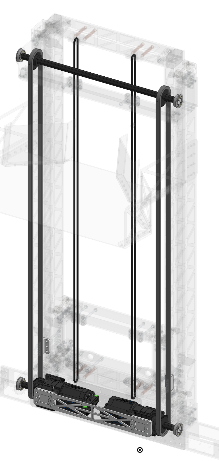
Transparent CAD view tracing the elevator's chain and Dyneema string paths from the motors to the upper stage
Chain drives the first stage; Dyneema string routes the second.
CAD close-up of two Kraken X60 motors, lower drive shaft, and a lightweighted motor mounting plate
Lower drive assembly: twin X60 motors, gearbox packaging, and the lightweighted support plate.

The difficult part was making the subsystem belong to the robot.

Starting from an existing architecture let us focus on fit, sourcing, stiffness, and repairability under a competition schedule. The work linked a CAD model to manufactured parts and a physical assembly, while showing how the elevator’s location constrained the pivot arm and the rest of the robot.

Next in this mechanism thread Off-season Elevator V2

Iteration documentation and imagery are still being gathered.

Return to FRC mechanisms